Cpu spread spectrum
Содержание:
Телекоммуникации
Расширенный спектр обычно использует структуру последовательного шумоподобного сигнала для расширения обычно узкополосного информационного сигнала по относительно широкополосному (радио) диапазону частот. Приемник коррелирует полученные сигналы, чтобы извлечь исходный информационный сигнал. Первоначально было две мотивации: либо противостоять попыткам противника заглушить связь (anti-jam, или AJ), либо скрыть тот факт, что связь вообще имела место, что иногда называется низкой вероятностью перехвата (LPI).
Расширенный спектр со скачкообразной перестройкой частоты (FHSS), расширенный спектр с прямой последовательностью (DSSS), расширенный спектр со скачкообразной перестройкой частоты (THSS), расширенный спектр со скачкообразной перестройкой частоты (CSS) и комбинации этих методов являются формами расширенного спектра. Первые два из этих методов используют последовательности псевдослучайных чисел, созданные с помощью генераторов псевдослучайных чисел, для определения и управления шаблоном распространения сигнала по выделенной полосе пропускания. Стандарт беспроводной связи IEEE 802.11 использует в своем радиоинтерфейсе либо FHSS, либо DSSS.
- Методы, известные с 1940-х годов и используемые в военных системах связи с 1950-х, «распространяют» радиосигнал в широком диапазоне частот, на несколько значений выше минимального требования. Основным принципом расширенного спектра является использование шумоподобных несущих волн, и, как следует из названия, ширина полосы пропускания намного шире, чем требуется для простой двухточечной связи с той же скоростью передачи данных.
- Устойчивость к заклиниванию (помехам). Прямая последовательность (DS) хороша для противодействия непрерывным узкополосным помехам, тогда как скачкообразная перестройка частоты (FH) лучше противодействует импульсным помехам. В системах DS узкополосные помехи влияют на эффективность обнаружения примерно так же, как если бы мощность помех распределена по всей ширине полосы сигнала, где она часто не намного сильнее фонового шума. Напротив, в узкополосных системах, где ширина полосы сигнала мала, качество принимаемого сигнала будет значительно снижено, если мощность помех будет сосредоточена в полосе пропускания сигнала.
- Устойчивость к подслушиванию . Последовательность расширения (в системах DS) или шаблон скачкообразной перестройки частоты (в системах FH) часто неизвестны тем, для кого сигнал является непреднамеренным, и в этом случае он скрывает сигнал и снижает вероятность того, что злоумышленник его поймет. Более того, для данной спектральной плотности мощности шума (PSD) системы с расширенным спектром требуют того же количества энергии на бит перед расширением, что и узкополосные системы, и, следовательно, такое же количество мощности, если скорость передачи данных перед расширением одинакова, но поскольку сигнал мощность распространяется на большую полосу пропускания, PSD сигнала намного ниже — часто значительно ниже, чем PSD шума — так что злоумышленник может быть не в состоянии определить, существует ли сигнал вообще. Однако для критически важных приложений, особенно тех, которые используют коммерчески доступные радиостанции, радиостанции с расширенным спектром не обеспечивают адекватной безопасности, если, как минимум, не используются длинные нелинейные последовательности расширения и сообщения не зашифрованы.
- Устойчивость к выцветанию . Большая полоса пропускания, занимаемая сигналами с расширенным спектром, обеспечивает некоторое частотное разнесение; т. е. маловероятно, что сигнал столкнется с серьезным замиранием из-за многолучевого распространения по всей его полосе пропускания. В системах с прямой последовательностью сигнал может быть обнаружен с помощью приемника граблей .
- Возможность множественного доступа, известная как множественный доступ с кодовым разделением (CDMA) или мультиплексирование с кодовым разделением (CDM). Несколько пользователей могут передавать одновременно в одной и той же полосе частот, если они используют разные последовательности расширения.
TWEETS
- IanCutress: @jasondunn @AndyMLC @Apple I have had ear buds, but I find the battery life appalling. I probably wear my Enco Q1s… https://t.co/K7uv826JVe
- IanCutress: @Krewell I run games rendered on CPUs. Does that count
- ganeshts: A Thunderbolt 4 / USB4 hub from @plugable at a very attractive price point (considering the USBC-HDMI value add). A… https://t.co/DiJZS8MmF9
- IanCutress: @OliFeeloo @jasondunn @AndyMLC @Apple I feel you’ve missed my point and drawn your own conclusion here.
- IanCutress: @AndyMLC @jasondunn @Apple To be honest, that’s happened to me… once? And I found a power point before I found a… https://t.co/fXbi2oM5rm
-
IanCutress: My turn:
‘From the nature of a continual Sisyphean task, our effervescent soda is indicative of a forest clearing devoid of wrist watches.’
- RyanSmithAT: @andreif7 If you’re not already, use iTunes to do it. For whatever reason it goes a lot faster that way than having… https://t.co/Be9IMU4gja
- andreif7: @spaspxa That’s not really true, they’re still way faster than iOS updates.
- andreif7: https://t.co/6bWtsZp3uI
- andreif7: @blu51899890 I’m looking at this and wondering how easy he makes that black gunk removal look, and also thinking to… https://t.co/63uzxd9mr4
- andreif7: @BlackMagicianX Nope. The display power between the two phones was identical. The battery capacity when charging wa… https://t.co/LB6tFEOhrq
- andreif7: @fivemack I heard that customer reception was extremely bad on that part.
-
RyanSmithAT: @chrisheinonen Aww man, sorry to hear you caught it.️
FWIW, I’m a week clear of COVID, and while all of the main… https://t.co/I61dHXOZwn
- RyanSmithAT: @jarredwalton Aw phooey, not you too! There are worse diseases, but COVID is certainly not an enjoyable experience.… https://t.co/Q6TI7c5CZo
- RyanSmithAT: RT @anandtech: Today Xiaomi announces the 11T and 11T Pro — a Dimensity 1200 and a Snapdragon 888 variant the same phone, characterised by…
- RyanSmithAT: @jemdavies Congrats Jem
- ganeshts: @JamesDSneed @IanCutress Yes, NAND has the ability to store dynamic sector remap information — this is not only for… https://t.co/J0NYC9oCZk
- ganeshts: @AG_1138 Micron has a history of doing these silent changes. The P2’s silent move from TLC to QLC resulted in worse… https://t.co/UfmTilvFi1
- ganeshts: @ricswi Looks like that requirement is Home-only. Other editions will still allow local accounts. I can’t remember… https://t.co/qOvPnduAuY
- ganeshts: @Laughing_Man @hnpn914 Benson, is there an update planned for the Twinkie PD to support EPR? I still use the USBC-T… https://t.co/D6g5nmQvB5
Follow @ANANDTECH
Taktsignalerzeugung
Spreizspektrum eines modernen Schaltnetzteils (Aufheizzeit) inkl. Wasserfalldiagramm über einige Minuten. Aufgenommen mit einem NF-5030 EMC-Analyzer
Spread-Spectrum-Takterzeugung (SSCG) wird in einigen synchronen digitalen Systemen verwendet , insbesondere solchen, die Mikroprozessoren enthalten, um die spektrale Dichte der elektromagnetischen Interferenz (EMI), die diese Systeme erzeugen , zu reduzieren . Ein synchrones digitales System ist eines, das von einem Taktsignal angesteuert wird und aufgrund seiner periodischen Natur ein unvermeidlich schmales Frequenzspektrum hat. Tatsächlich würde bei einem perfekten Taktsignal seine gesamte Energie auf eine einzige Frequenz (die gewünschte Taktfrequenz) und seine Harmonischen konzentriert sein. Praktische synchrone Digitalsysteme strahlen elektromagnetische Energie auf einer Reihe von schmalen Bändern ab, die auf die Taktfrequenz und ihre Oberwellen gespreizt sind, was zu einem Frequenzspektrum führt, das bei bestimmten Frequenzen die gesetzlichen Grenzwerte für elektromagnetische Störungen überschreiten kann (z. B. die der FCC in den Vereinigten Staaten). Staaten, JEITA in Japan und IEC in Europa).
Die Spread-Spectrum-Taktung vermeidet dieses Problem, indem eines der zuvor beschriebenen Verfahren verwendet wird, um die abgestrahlte Spitzenenergie und daher ihre elektromagnetischen Emissionen zu reduzieren und so die Vorschriften zur elektromagnetischen Verträglichkeit (EMV) einzuhalten.
Es ist zu einer beliebten Technik geworden, um eine behördliche Zulassung zu erhalten, da es nur eine einfache Modifikation der Ausrüstung erfordert. Aufgrund schnellerer Taktraten und der zunehmenden Integration hochauflösender LCD-Displays in immer kleinere Geräte ist es in tragbaren elektronischen Geräten noch beliebter. Da diese Geräte leichtgewichtig und kostengünstig sind, sind herkömmliche passive elektronische Maßnahmen zur Reduzierung von EMI, wie Kondensatoren oder Metallabschirmungen, nicht praktikabel. In diesen Fällen sind aktive EMI-Reduktionstechniken wie Spread-Spectrum-Taktung erforderlich.
Allerdings kann die Spread-Spectrum-Taktung, wie andere Arten der dynamischen Frequenzänderung , auch Herausforderungen für Designer darstellen. Das wichtigste davon ist die Takt-/Daten-Fehlausrichtung oder Taktversatz . Folglich wird eine Fähigkeit zum Deaktivieren der Spread-Spectrum-Taktung in Computersystemen als nützlich angesehen.
Beachten Sie, dass diese Methode die gesamte abgestrahlte Energie nicht reduziert und daher Systeme nicht unbedingt weniger wahrscheinlich Interferenzen verursachen. Das Verteilen von Energie über eine größere Bandbreite reduziert effektiv elektrische und magnetische Messwerte innerhalb schmaler Bandbreiten. Typische Messempfänger von EMV-Prüflaboren unterteilen das elektromagnetische Spektrum in ca. 120 kHz breite Frequenzbänder. Wenn das zu testende System seine gesamte Energie in einer schmalen Bandbreite abstrahlen würde, würde es einen großen Peak registrieren. Die Verteilung derselben Energie auf eine größere Bandbreite verhindert, dass Systeme genug Energie in ein Schmalband einspeisen, um die gesetzlichen Grenzwerte zu überschreiten. Die Nützlichkeit dieser Methode als Mittel zur Reduzierung von Interferenzproblemen in der Praxis wird oft diskutiert, da angenommen wird, dass die Spread-Spectrum-Taktung Probleme mit höherer Strahlungsenergie durch einfaches Ausnutzen von Lücken in der EMV-Gesetzgebung oder Zertifizierungsverfahren verbirgt anstatt sie zu lösen. Diese Situation führt dazu, dass elektronische Geräte, die auf schmale Bandbreite(n) empfindlich reagieren, viel weniger Interferenzen erfahren, während Geräte mit Breitbandempfindlichkeit oder sogar bei anderen höheren Frequenzen (wie ein Radioempfänger, der auf einen anderen Sender eingestellt ist) mehr Interferenzen erfahren.
FCC-Zertifizierungstests werden oft mit aktivierter Spread-Spectrum-Funktion abgeschlossen, um die gemessenen Emissionen auf akzeptable gesetzliche Grenzen zu reduzieren. Die Spread-Spectrum-Funktionalität kann jedoch in einigen Fällen vom Benutzer deaktiviert werden. Im Bereich von Personalcomputern beispielsweise enthalten einige BIOS- Schreiber die Fähigkeit, die Spreizspektrum-Takterzeugung als eine Benutzereinstellung zu deaktivieren, wodurch das Ziel der EMI-Vorschriften umgangen wird. Dies könnte als Schlupfloch angesehen werden , wird aber im Allgemeinen übersehen, solange Spread-Spectrum standardmäßig aktiviert ist.
Recommended Reading
- IOQD from The Tech ARP BIOS Guide!
- SDRAM Trrd Timing Value from The Tech ARP BIOS Guide!
- VGA Share Memory Size from The Tech ARP BIOS Guide!
- Hard Disk Pre-Delay from The Tech ARP BIOS Guide!
- AMD Radeon Pro W5700 : Everything You Need To Know!
- AMD Athlon 3000G : The Last Raven Ridge APU Unlocked!
- 3rd Gen AMD Threadripper : Everything You Need To Know!
- AMD Ryzen 9 3950X : EVERYTHING You Need To Know!
- Write Data In to Read Delay from The Tech ARP BIOS Guide!
- NX Technology from The Tech ARP BIOS Guide!
- V-Link Data 2X Support From The Tech ARP BIOS Guide!
- AGPCLK / CPUCLK from The Tech ARP BIOS Guide!
- CPU / DRAM CLK Synch CTL – The Tech ARP BIOS Guide!
- AMD Radeon RX 5500 Series : Everything You Need To Know!
- Cooler Master COSMOS C700P Black Edition Revealed!
- The Tech ARP Mobile GPU Comparison Guide
- IDE Bus Master Support from The Tech ARP BIOS Guide!
- The Acer Predator Thronos Air Gaming Cockpit Revealed!
- Cooler Master MasterBox CM694 Details Revealed!
- CPUID Maximum Value Limit from The Tech ARP BIOS Guide!
- The NVIDIA ACE Design For Creator Laptops Explained!
- Bank Swizzle Mode from The Tech ARP BIOS Guide
- Master Priority Rotation from The Tech ARP BIOS Guide!
- RW Queue Bypass from The Tech ARP BIOS Guide
- AGP Capability from The Tech ARP BIOS Guide
- PCI Clock Synchronization Mode – The Tech ARP BIOS Guide
- The Intel Core Processor Number Guide – What They Mean!
- 10th Gen Intel Comet Lake : 1 Step Forward, 1 Step Back!
- 10th Gen Intel Ice Lake Mobile CPU Features + Specifications!
- The 10th Gen Intel Core Processor Number Guide!
PCM RC Radios
PCM stands for Pulse Code Modulation and works by
embedding a digital signal within the basic FM radio wave. A digital
processor chip inside the RC radio will encode a digital transmission
and send it out on a standard narrow band FM carrier wave. The receiver
also has a processor chip that decodes this digital data back into a
usable analog signal for the servos.
Think of this like hearing a bunch of people talking to you in
different languages but you only understand one of those languages. Our
brains have the ability to filter out all the other noise and only
respond to the information from the language we know and understand.
This method all but eliminates any glitching caused by electrical
noise because unless the receiver “hears” a digital command that it
understands, it won’t respond. It is this ability to ignore outside
interference that makes PCM so perfect for all kinds of RC control –
especially for helicopters. This brings us to the topic of “Fail Safe”.
Like I just mentioned, a PCM RC radio receiver can ride out
interference because it doesn’t understand it and simply ignores it.
This makes it possible to add a secondary feature to that ability. Fail
Safe is a safety function that allows you to “tell” or “teach” the
receiver what to do if it no longer sees or understands the radio
signals it receives.
No, this doesn’t mean the receiver is capable of flying and then
landing your helicopter if there is radio signal corruption, but it will
move the servos to a predetermined value. For safety reasons that
usually means throttle off and all other control functions at neutral or perhaps last position.
So does all that mean that PCM RC radio systems are immune to
interference? I am afraid not. If another PCM radio is transmitting on
the same frequency, you will certainly get interference – your receiver
will see conflicting signals.
Even a standard FM (PPM) RC radio will cause loss of control
issues if it’s on the same frequency. Your PCM receiver won’t understand
this FM noise of course, but it also won’t be able to “hear” your PCM
radio’s digital voice over all the noise (called high noise floor in the RF world). Let’s go back to the illustration of all those people talking to
us in different languages. If there are too many, the noise floor is so bloody loud, you
can’t hear the person talking to you in your own language right?
Communication is lost.
Принцип работы
Как известно, персональный компьютер – это сложное устройство, содержащее множество микросхем и электронных компонентов, потребляющих много энергии и способных излучать в окружающее пространство во время своей работы мощные электромагнитные волны в радиодиапазоне. Эти волны далеко не всегда безобидны, поскольку они могут, благодаря физическому явлению интерференции, приводить к нарушению работы находящихся рядом с компьютером электромагнитных приборов и устройств, таких, например, как телевизоры, радиоприемники, и.т.д.
Данное явление принято называть электромагнитными помехами (Electromagnetic Interference). Для борьбы с электромагнитными помехами было разработано немало способов. В случае персонального компьютера большинство из создаваемых его электронными компонентами помех успешно экранируется металлическим корпусом, однако часто этого бывает недостаточно.
Кроме того, конструкторы при разработке электронных устройств стремятся к тому, чтобы минимизировать негативное влияние электромагнитных помех. Для этого различные устройства, функционирующие поблизости друг от друга (а это могут быть, в частности, и внутренние элементы компьютера), проектируются таким образом, чтобы они соответствовали бы требованиям электромагнитной совместимости.
Также в компьютерной индустрии существует ряд строгих стандартов на количество создаваемых элементами компьютера помех. Эти стандарты в разных регионах регулируются такими организациями, как FCC, JEITA и IEC.
Одним из методов борьбы с электромагнитными помехами, создаваемыми компьютером, также является метод расширения спектра электромагнитного излучения(Spread Spectrum). Суть его заключается в следующем. Наибольшие электромагнитные помехи из всех компонентов, расположенных внутри компьютера, создает микросхема тактового генератора. Эта микросхема обеспечивает работу процессора, а также многих шин, которые связывают процессор с другими устройствами, такими, как оперативная память или устройства ввода-вывода. При работе тактового генератора создается ряд очень мощных электромагнитных помех, максимумы которых приходятся на пики тактовых сигналов. Однако если распределить энергию, излучаемую на максимуме тактового сигнала, в более широком диапазоне, сделав форму сигнала более отлогой, то максимальная величина электромагнитных помех в большинстве случаев не будет превышать заранее установленного безопасного значения.
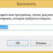
Для реализации данного метода в BIOS многих производителей включены опции управления распределением спектра электромагнитного излучения. Примером такой опции является опция CPU Spread Spectrum, которая обычно входит в состав группы опций, предназначенных для установки параметров распределения спектра для различных шин компьютера. Она позволяет включить или выключить функцию распределения спектра для шины процессора. В отличие от такой широко распространенной опции, как Spectrum, данная опция не затрагивает другие шины персонального компьютера, такие, как шины PCI/PCI-E/AGP, IDE/SATA и т.д. Включение опции осуществляется при помощи выбора значения Enabled, а выключение – при помощи значения Disabled.
Функции
- DSSS фазовых сдвиги- синусоидальная волна псевдослучайные с непрерывной строкой чипов, каждый из которых имеет значительно меньшую длительность , чем информационный бит . То есть каждый информационный бит модулируется последовательностью гораздо более быстрых чипов. Следовательно, чиповая скорость намного выше, чем битовая скорость информации .
- DSSS использует структуру сигнала, в которой последовательность расширения, создаваемая передатчиком, уже известна приемнику. Затем приемник может использовать ту же последовательность расширения, чтобы противодействовать ее влиянию на принятый сигнал, чтобы восстановить информационный сигнал.
Introduction to PCIE Spread Spectrum Clock (SSC)
SSC is a technology that slowly modulates the clock frequency in order to reduce the EMI emission at the center frequency. With SSC, the radiated energy will not produce 2.5GHz or 5GHz noise spikes because the radiation is dispersed to small frequencies around the center frequency Range. (https://www.cnblogs.com/cute/archive/2011/05/27/2059631.html)
The SSC spread spectrum clock is optional for PCIe, not mandatory. If you choose to support spread spectrum clocks, the following requirements must be met (https://www.sohu.com/a/367547389_781333):
-
The modulation range is +0% to -0.5%, that is, Down Spreading, as shown in the figure below
-
The modulation frequency must be between 30KHz and 33KHz, usually a triangular wave
-
The jitter of the reference clock source (Jitter) must be within 300ppm
The frequency change curve of the reference clock with SSC is shown in the figure below:
Использует
- Спутниковые навигационные системы США GPS , европейская Galileo и российская ГЛОНАСС ; ранее ГЛОНАСС использовал DSSS с одной последовательностью расширения в сочетании с FDMA , а позже ГЛОНАСС использовал DSSS для достижения CDMA с несколькими последовательностями расширения.
- DS-CDMA (Множественный доступ с прямым последовательным кодовым разделением каналов) — это схема множественного доступа , основанная на DSSS, путем распределения сигналов от / к разным пользователям с разными кодами. Это наиболее широко используемый тип CDMA .
- Беспроводные телефоны , работающие в 900 МГц, 2,4 ГГц и 5,8 ГГц полосы
- IEEE 802.11b 2,4 ГГц Wi-Fi и его предшественник 802.11-1999 . (Их преемник 802.11g использует как OFDM, так и DSSS)
- Автоматическое считывание показаний счетчика
- IEEE 802.15.4 (используется, например, как уровень PHY и MAC для ZigBee или как физический уровень для WirelessHART )
- Радиоуправляемая модель Автомобильная, авиационная и морская техника
Quellen
- Dieser Artikel enthält gemeinfreies Material aus dem Dokument General Services Administration : (zur Unterstützung von MIL-STD-188 )
- NTIA-Handbuch mit Vorschriften und Verfahren für das bundesstaatliche Hochfrequenzmanagement
- Nationales Glossar zur Sicherheit von Informationssystemen
- Geschichte des Spread-Spektrums, wie in «Smart Mobs, The Next Social Revolution», Howard Rheingold , ISBN 0-7382-0608-3
- Władysław Kozaczuk , Enigma: How the German Machine Chiffre Was Broken, and How It Was Read by the Allies in World War Two , herausgegeben und übersetzt von Christopher Kasparek , Frederick, MD, University Publications of America, 1984, ISBN 0-89093-547 -5 .
- Andrew S. Tanenbaum und David J. Wetherall, Computernetzwerke , Fünfte Auflage.
AM RC Radios
AM stands for amplitude modulation. This is the most
basic and very first method used for controlling RC models.
AM RC radios
send information to the model by changing the amplitudes of a base
carrier wave at a specific frequency.
It is then a simple mater for the receiver to filter the highs
and lows of the changing amplitudes of the carrier wave into usable
information.
The problem is it is really easy for those amplitude highs
and lows to be affected by almost any electrical noise generating
device.
Any type of electrical or metal on metal noise from lighting to
car ignition systems will result in interference (just listen to an AM
radio station while an electric motor in your house is running or an
electrical storm is approaching – big time noise).
It is all these sources of interference that will cause loss of
control issues on your RC model. This holds especially true for all
types of RC helicopters with the many metal on metal contact points,
electronic speed controllers and motors in
electric RC helis
, and high voltage
ignition systems
on
gas powered RC helis
.
Bottom line – stay away from AM RC radios for RC helicopters at all costs. I guarantee you will have interference issues. Yes I know this from experience.
How Does A Spread Spectrum Radio System Work?
There are essentially two different types of spread spectrum technologies that today’s 2.4GHz RC radios use… FHSS & DSSS.
FHSS:
FHSS is exactly how that first WWII
spread spectrum system worked.
Frequency hopping, as the name suggests,
transmits within a specific frequency band (such as 2.4 GHz), but changes the precise frequency of the
transmission hundreds of times a second. It’s kinda like switching between channels on your TV (channel hopping) if the same show was on several different channels at the same time and you were trying to avoid any commercials for a commercial free watching experience. The commercials in the TV example here are interference.
For FHSS to work, the receiver
has to know the frequency changing pattern so it can hop to the
different frequencies in the same order and time frame as the
transmitter does. The time spent on each specific frequency is so short, even if there was interference on several of the frequencies, it changes so quick, you wouldn’t detect it.
FHSS theoretically has better interference immunity than DSSS as more channels are used to hop around on but the flip side of that coin is a FHSS only RC radio would have very poor/limited range due to something called «Process Gain». Yep, even radio brands that «market» their radios as using FHSS technology are not telling us the whole story since they also use DSSS. All our spread spectrum RC radios use DSSS technology. Some combine it with FHSS is all.
Direct Sequence Spread Spectrum
DSSS:
Unlike
frequency hopping, direct sequence as the name suggests uses random PN
code sequences and picks one or more pseudo randomly selected frequencies out within the band (such as 2.4 GHz).
The idea is with several randomly selected frequencies, along with random code sequences, it’s very unlikely all of them would ever experience interference at the exact same time within the unique code sequence. Using our TV example from above, DSSS would be somewhat similar to watching several TV’s with the same show on each TV all on different channels.
At any one time, commercials will be on some of the channels, but never on all of them at the same time allowing you to watch your show commercial (interference) free by simply looking at (processing) all the TV images and ignoring any that were commercials. This brings us to DSSS main contribution our hobby — improved radio range. I touched on Process Gain above in the FHSS discussion, but this is why DSSS technology must be used in all 2.4GHz RC radio’s regardless of brand.
DSSS is capable of high bit processing speeds and the higher the bit process rate, the greater that range can be with a set amount of transmitter output power (which by the way is pretty low for off the shelf RC radios). It’s not that a DSSS RC radio signal will travel any further out than the same powered signal using FHSS or just plain old 2.4GHz noise of the same power level; but due to the higher bit processing rate, it can process and extract more clean data packets out of that noisy environment — even as the signal gets weak at extended ranges.
These are very, very basic explanations of both spread spectrum methods
and for most of us, it’s simply enough knowing that the systems work, and work well.
If you want a more technical explanation of how both FHSS
and DSSS work in relation to RC radio’s, one of my web visitors (who is an accomplished electrical engineer) has written a wonderful article entitled «RC Spread Spectrum Demystified» and allowed me to share it on my site (click on that link to be taken to the article).
It’s a really great read if you truly want to understand how all our spread spectrum RC radios operate regardless of brand. It also puts to rest much of the marketing hype and misinformation floating around out there (I sure learned a few things that changed what I thought I understood after reading it).
Bruce’s good video below provides an easy to understand explanation of how DSSS works.